Impedance matching analysis: principle, impact, and engineering practice
When debugging high-speed circuits, we often encounter issues such as signal waveform distortion, overshoot, ringing, or insufficient system output power and decreased sensitivity. Behind these problems, one of the most common and crucial reasons is impedance mismatch. When there is impedance mismatch between the transmitting end and the transmission line, or between the transmission line and the receiving end, reflections occur. These reflected signals can disrupt the original output signal and superimpose on it, resulting in the aforementioned series of problems.
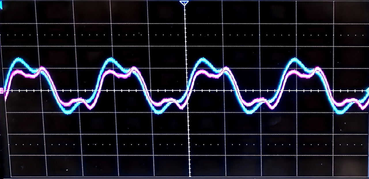
Figure 1 Distortion caused by signal reflection
This article will systematically explain how impedance matching affects signals and how to achieve matching in engineering, starting from the principles.
1. What is impedance?
Impedance is a complex number, denoted by Z. Z=R+jX, where the real part represents resistance and the imaginary part represents reactance. Capacitive reactance and inductive reactance are collectively referred to as reactance.
In practical applications, the signal source is not an ideal source; it also has impedance. Transmission lines have characteristic impedance, which is determined by distributed inductance and capacitance and is independent of length. When the signal wavelength is the same as the length of the conductor, the conductor is considered as a transmission line.
2. What is impedance matching?
Definition of impedance matching: The impedance of the signal source = the characteristic impedance of the transmission line = the load impedance, that is
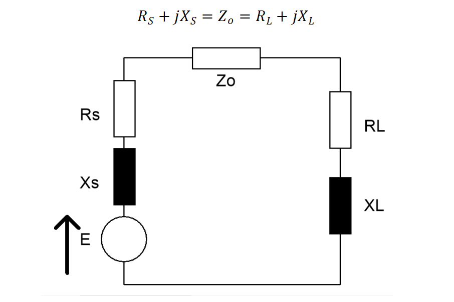
Figure 2 Schematic diagram of impedance matching
3. How to achieve impedance matching?
L-type matching network
An L-type matching network, as the name suggests, consists of two reactive components (inductance L and capacitance C) connected in a shape resembling the letter "L". Its core function is to transform a complex impedance (such as R + jX) into another desired impedance (usually a pure resistor, i.e., the characteristic impedance Z0 of the system, such as 50Ω) at a specific frequency.
L-type matching method 1: left L, this matching is applicable when Rs > RL.
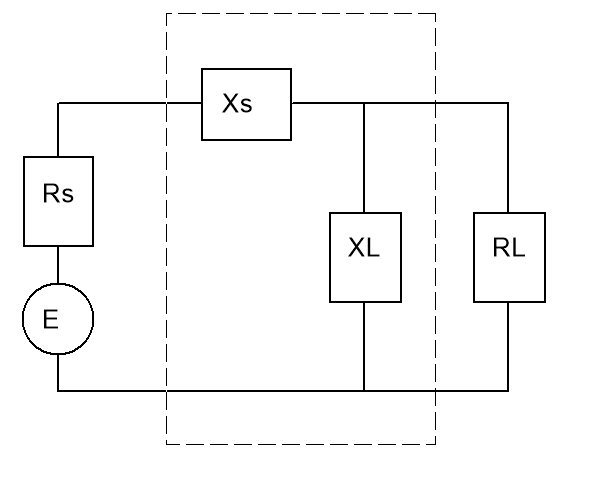
Figure 3 Schematic diagram of left L matching
L-shaped matching method 2: Right L, this matching is applicable when Rs < RL.
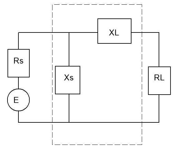
Figure 4 Schematic diagram of right L matching
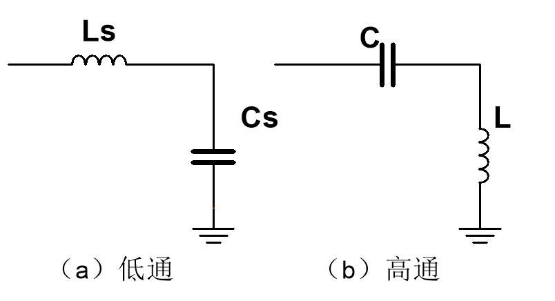
For these two methods, they can be categorized as either the Ls-Cp low-pass form or the Cs-Lp high-pass form
Transmission line matching
The λ/4 impedance transformer is often used, and the characteristic impedance Z0' of this transmission line satisfies:
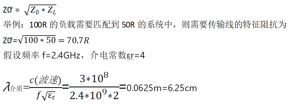
Therefore, it is necessary to design a transmission line with a length of 1.56cm and a characteristic impedance of 70.7Ω for matching.
By combining the above two methods of L-type matching and transmission line matching, impedance matching can be achieved between the source and the transmission line, as well as between the transmission line and the load.
Impedance matching is crucial in engineering design, particularly in high-speed circuits, where it plays an irreplaceable role in ensuring power transmission efficiency, signal integrity, and electromagnetic compatibility.