
Square wave driving capacitive load: detailed explanation of power amplifier bandwidth and current demand

In electronic system testing and design, engineers often utilize power amplifiers to drive capacitive loads such as CBB capacitors, MLCC capacitors, or transmission cables. When the input signal is a square wave, a common confusion arises: why does an amplifier with sufficient nominal power exhibit waveform distortion, ringing, or even trigger overcurrent protection when actually driving a capacitive load?
The root of the problem often lies not in the rated power of the amplifier, but in the interaction between its bandwidth and output current capability under capacitive loading.
1. Electrical characteristics of capacitors
ic(t) = C·dv(t)/dt
Where: ic(t) represents the instantaneous current, and C denotes the capacitance value
dv(t)/dt represents the rate of change of voltage across the capacitor
This formula clearly indicates that to establish a rapidly changing voltage for the capacitor, a huge instantaneous current must be provided.
2. Constraints of quantization, bandwidth, and slew rate
The rise time tr of an actual square wave (the time from 10% Vm to 90% Vm) is a direct manifestation of bandwidth. An empirical formula commonly used in engineering is: BW ≈ 0.35/tr. Essentially, it represents the bandwidth's ability to amplify high-frequency details, which is translated into a time constraint on voltage rise.
The essence of slew rate is the physical limitation imposed by the limited current within the amplifier on the charging and discharging speed of the compensation capacitor.
When the slew rate is greater than or equal to the upper limit of dv/dt corresponding to the bandwidth, the bandwidth becomes the dominant constraint; if the slew rate is lower, the current is determined by the slew rate, and the bandwidth constraint is invalidated.
The actual maximum dv/dt is determined by the minimum of the upper limit of dv/dt corresponding to the bandwidth and the slew rate, which in turn determines the peak value of capacitive load current.
3. Analogize from "square wave edge" to "sine wave"
When driving a capacitive load, the most severe test occurs at the moment when the voltage changes the fastest, namely the rising edge and falling edge of the square wave. The high-frequency characteristics of this rapidly changing edge can be approximated by a sine wave with an equivalent frequency, and the sine wave has the "fastest voltage change" near its "peak value". The dv/dt values at these two "fastest change moments" can be approximately equal in engineering practice.
From a time-domain perspective: When the slew rate dominates, the equivalent frequency f equals fSR, which is equal to SR divided by πV_p. When bandwidth dominates, the peak current is determined by ic(t) = C * dv/dt, where the actual dv/dt is limited by the power amplifier's bandwidth, meaning the equivalent frequency f equals the bandwidth frequency fBW.
From the perspective of the frequency domain: At the maximum frequency, the impedance of the capacitor, Xc = 1/(2πfC), determines the magnitude of the current.
4. Actual cases
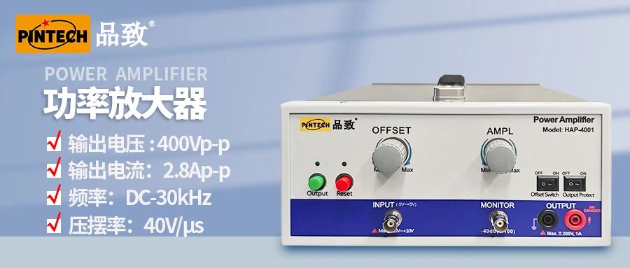
Power amplifier model: HAP-4001
Power amplifier bandwidth and slew rate: 30kHz, 40V/us
Output voltage: Outputting a 40Vp square wave with a frequency of 2kHz
Load CBB capacitor: 100nF
Calculate instantaneous peak current:
At 40Vp, the upper limit of dv/dt corresponding to 30kHz is V_pp·BW/0.35=6.8V/us
The actual maximum dv/dt is equal to the minimum of 6.8V/us and 40V/us, which is 6.8V/us,
The actual output bandwidth dominates, i.e., f=fBW
Xc =1/(2πf C) ≈50Ω
I_p = V_p / Xc = 40V /50Ω ≈ 800mAp
The actual measured current peak value is 950 mAp, which is within the error range
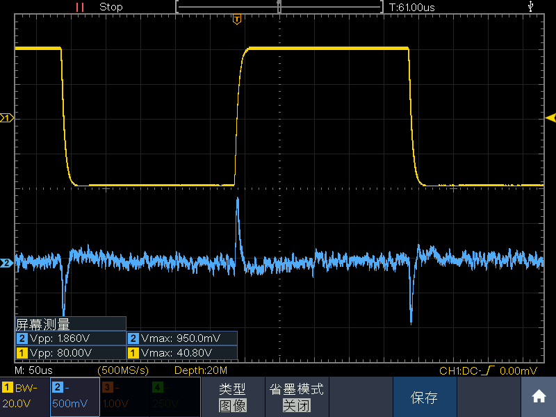
The yellow line in the diagram represents the voltage waveform, while the blue line represents the current waveform
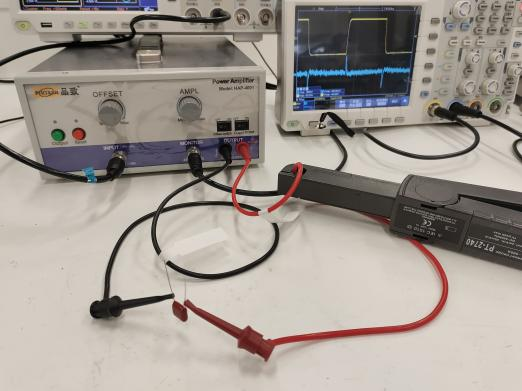
Wiring Diagram
5. Summary
When a power amplifier drives a capacitive load (such as a CBB capacitor) and inputs a square wave, a very large instantaneous current is required to respond to the rising/falling edges of the square wave. The degree of this instantaneous current demand, under sufficient slew rate conditions, depends on the bandwidth of the power amplifier. The lower the bandwidth, the slower the square wave edges, the smaller the instantaneous current demand, but the more severe the waveform distortion; the higher the bandwidth, the steeper the square wave edges, the greater the instantaneous current demand, but the more faithful the waveform.
In practical applications, if it is necessary to drive a large capacitive load, besides selecting a power amplifier with high voltage slew rate and high current, one could also consider connecting a small resistor in series at the output to dampen oscillations. However, this will further limit the available bandwidth and current.