
What is Common-Mode Rejection Ratio
Common-Mode Rejection Ratio Explained
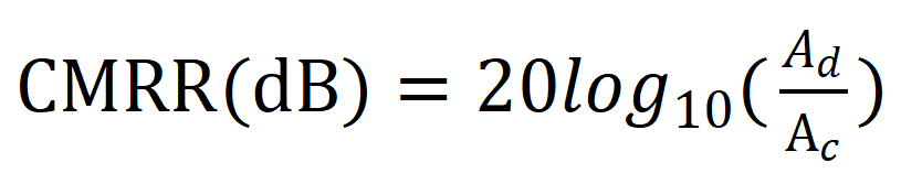
In the probe's data manual, the common-mode rejection ratio (CMRR) performance parameter is one of the core metrics. It is typically expressed in decibels (dB), with the calculation formula as follows:
Among these,
Ad represents the differential-mode voltage gain(The ability to amplify useful signals; when paired with a 10x attenuator, Ad = 0.1).
AC represents common-mode voltage gain(The amplification factor for common-mode signals should ideally approach zero).
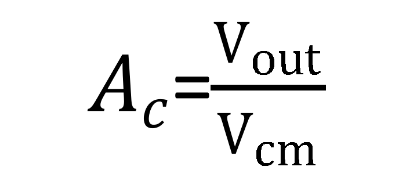
By definition, the formula for calculating common-mode voltage gain is:
Among these,
Vout is the output voltage of the probe(set the oscilloscope to x1).
Vcm is the common-mode voltage of the probe input.
So,

Our optical isolation products achieve CMRR exceeding 120dB at DC or low frequencies. This article demonstrates how to measure the common-mode rejection ratio of probes using an optical isolation probe:
Preparation of Equipment
30kV Amplifier: HA-30K
Optically Isolated Probe: PTO350 with X10 Attenuator
High-Frequency Oscilloscope: MDO7500A
Signal Generator: DG5100
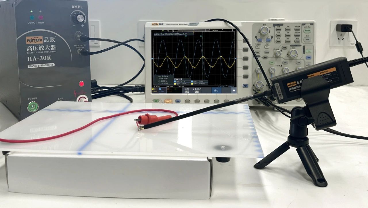
Assemble the peripheral circuit: Short-circuit the two terminals at the front end of the X10 attenuator and connect them to the output of the 30kV amplifier.
The simulation results are shown below. Test conditions: 60Hz, approximately 10kVrms. Calculations are based on Vp-p. Channel 2 shows the common-mode voltage Vcm from input to probe, approximately 28.21kVpp (oscilloscope set to x2, actual scaling is x2000). Channel 1 shows the output voltage Vout from the probe, approximately 2.325mVpp (oscilloscope set to x1).
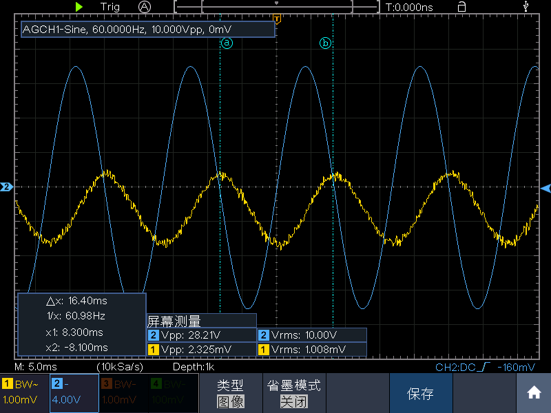
Calculated according to the above formula: When paired with a 10x attenuator, the input and output of the optical isolation probe correspond as follows:

The above describes the experimental procedure for measuring the common-mode rejection ratio using an optically isolated probe.