
Analysis of the phenomenon of zero offset in high-voltage probes
In scenarios such as high-voltage DC ripple measurement, a common phenomenon is encountered: when using the same high-voltage probe paired with different oscilloscopes or just different channels to measure AC coupling, there are significant differences in the baseline zero position displayed on the screen. Some can return to zero normally, while others are not at zero. This deviation is not a device malfunction, but rather the result of the interaction of multiple circuit characteristics in the measurement system composed of the probe and oscilloscope.
1. Troubleshooting
Using DC coupling testing, operate according to specifications to connect the high-voltage probe to the oscilloscope and measure a 1kV DC power supply. If the oscilloscope can accurately display the waveform of the DC signal and the corresponding value of 1kV, it indicates that the probe is functioning properly, and the issue may lie with the oscilloscope.
2. Analysis
Differences in coupling capacitance characteristics
The coupling capacitors of different oscilloscope input circuits vary in parameters such as capacitance accuracy and leakage resistance. The core of AC coupling is to block DC through capacitors, and differences in capacitor performance can affect the zero state. If there is minor leakage or capacitance deviation in the capacitor, it can lead to incomplete isolation of the DC component, and the residual minor DC component will cause the baseline to deviate from the zero point. For example, if the coupling capacitor of an oscilloscope ages and the leakage resistance decreases, even when switched to AC coupling, there will still be a trace of DC signal passing through, causing a zero offset. However, oscilloscopes with good capacitor performance do not have this problem. Therefore, different channels or different oscilloscopes may have different offsets.
Differences in attenuation networks of probes
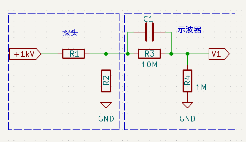
The core function of a high-voltage probe is achieved through resistive voltage division, as illustrated below. Different probes have different R1 and R2 values. For example, for an x1000 probe with an input impedance of 100MΩ, R1=100M and R2=111k; for an input impedance of 900MΩ, R1=900M and R2=9.1M; for an input impedance of 1G, R1=999M and R2=∞. When measuring a voltage of 1kV with AC coupling, if the leakage resistance R3 of the oscilloscope's internal AC coupling capacitor C1 is infinite, the DC component of V1 remains constant at zero. When R3=10M, the x1000 probe with 900M has an offset of approximately 500V, while the x1000 probe with 100M only has an offset of 100V. Therefore, different probes may have different offsets.
3. Summary
After excluding the fault of the high-voltage probe through DC coupling testing, it was found that the zero offset originated from differences in the relevant characteristics of the oscilloscope in the measurement system and environmental factors. It was mainly the result of the interaction between the coupling capacitance characteristics and attenuation network parameters of the oscilloscope and the measurement system composed of the probe. Clarifying this core logic can provide key directions for optimizing the measurement scheme and reducing zero offset in the future.