
Detailed explanation and application of amplifier slew rate
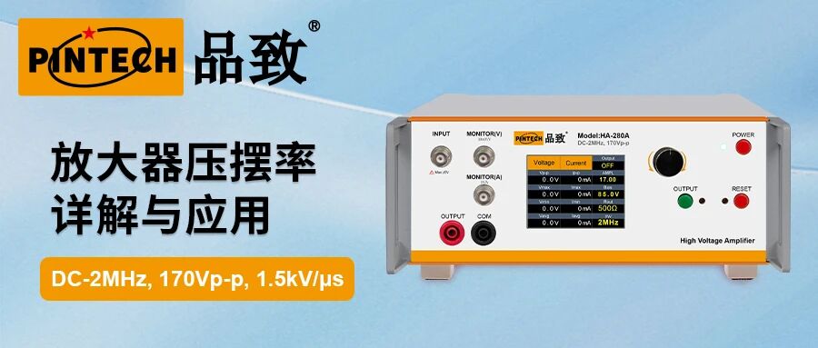
1、 The meaning of slew rate
Slew rate, also known as conversion rate, is the maximum rate at which the output voltage of an amplifier can change per unit time, measured in V/μ s. When a high-frequency signal with a large amplitude is input, if the theoretical speed of signal change exceeds the slew rate of the operational amplifier, the output waveform will be distorted. Sine waves will become triangular waves, and square waves will become trapezoidal waves.
Calculation formula: For sine waves, to avoid distortion of the slew rate, it is necessary to satisfy the following: slew rate SR ≥ 2 π fVp. For square waves, the slew rate should satisfy SR ≥ Δ V/Δ t, where Δ V is the voltage change and Δ t is the rise or fall time.
2、 How to choose an amplifier with a suitable slew rate
The core principle for selecting the slew rate is to ensure that the slew rate of the operational amplifier is higher than the maximum voltage change rate that the signal may experience in the application.
1. Determine Vp and f_max (or t_r rise time);
2. Calculate SR_min;
3. In addition to the slew rate, it is also necessary to confirm whether the gain bandwidth product of the amplifier meets the signal frequency requirements to avoid distortion caused by insufficient bandwidth when dealing with small signals;
4. Check other parameters, such as output voltage and current range, load upper limit, etc. For example, suppose a pulse from 0V to 200V needs to be generated, and the rise time t_r is required to be less than 1 μ s. SR_min ≥ 200 V/1 × 10 ^ -6 s=200 V/μ s. In this case, an amplifier with a slew rate higher than 200 V/μ s is required. To ensure compliance with requirements, models that are 20% -50% higher than the calculated value are usually chosen.
In addition, it is necessary to verify whether the gain bandwidth product of the amplifier meets the requirements of small signal frequency.
3、 How to measure and verify
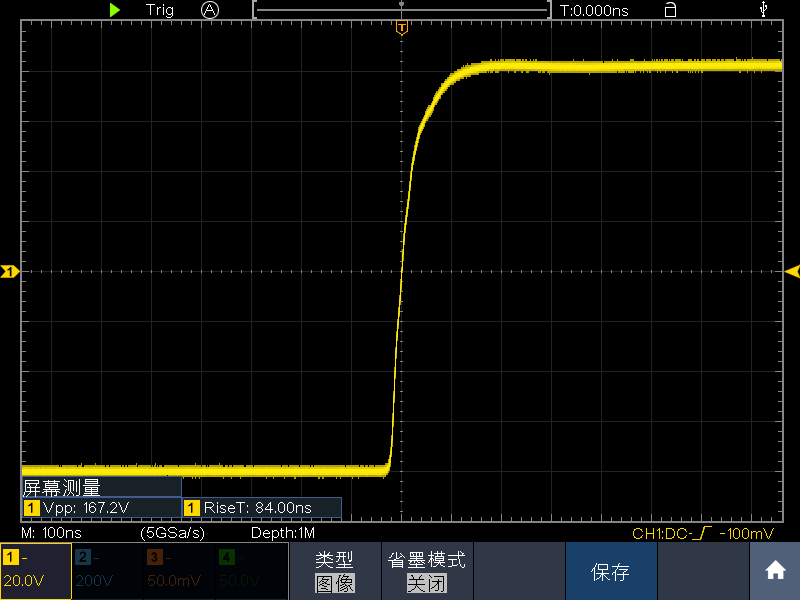
1. Set the high voltage amplifier to the desired gain (e.g. 20 times). Connect its input to the square wave output of the signal generator. Connect the output of the amplifier to one channel of the oscilloscope, and use a high bandwidth oscilloscope and probe to avoid errors introduced by the measurement system itself.
2. Apply a large amplitude square wave signal input, and the output square wave amplitude should be close to the maximum allowable value of the amplifier. For example, if the maximum output is 170Vpp, the test amplitude should be above 160Vpp. The input frequency should not be too high, usually within the range of 1kHz-10kHz.
3. Measurement and Calculation
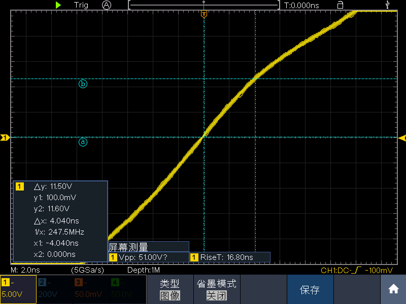
Capture the square wave waveform of the output on the oscilloscope. Using the cursor function of the oscilloscope, measure the time Δ t experienced during the fastest period of output voltage change. Generally, the maximum rate of change occurs at the zero crossing, and measure the amount of voltage change Δ V during this period.
For example, in the middle section of the 168Vpp square wave below, it was measured that 11.5/4.04ns ≈ 2.8kV/us.
4、 Application
In practical applications, it can be found that sometimes when a high-voltage amplifier is connected to a capacitive load, the slew rate will change, and the fundamental reason is current limitation. If the required current of the load is greater than the maximum output current of the amplifier, it will cause distortion of the output waveform, oscillation, and other situations.
Connecting capacitive loads will not change the theoretical slew rate of the amplifier itself, but will severely limit the actual output slew rate it can achieve. The final actual output slew rate is determined by the output current capability of the amplifier and the size of the capacitive load. Formula for driving capacitive load: Ip=C * dV/dt=C_load * SR.
If the required current of the load is calculated according to the formula to be less than the maximum output current of the amplifier, then the amplifier can operate normally, and the actual slew rate is equal to its theoretical slew rate. However, if the capacitive load C_load is large, or the theoretical slew rate SR is high, resulting in a theoretical value of C_load * SR>Imax. At this point, the output current is clamped at Imax. When the current is limited, the actual achievable output slew rate becomes: SR=Imax/C_load.
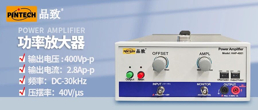
For example, the Pintech HA-4001 has a slew rate of 40V/us and a maximum output AC peak current of 1.4Ap. When driving 10nf, according to the formula I=CSR=10nF40V/? s=0.4A, the minimum current required to drive a capacitive load is 0.4Ap, which is much smaller than 1.4Ap. Therefore, the actual slew rate for driving is 40V/us.
Therefore, when driving large capacitive loads, it is not only important to consider the slew rate, but also to pay attention to its output current capability and choose an amplifier that is suitable for the output current.