
Differential Probe Input Range Analysis—A Critical Prerequisite for Accurate Measurement
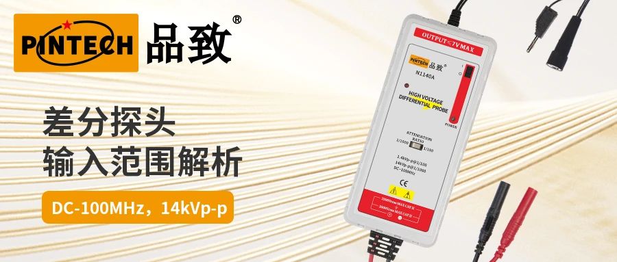
The safety and accuracy of differential probe measurements depend on controlling two critical parameters: the differential voltage range and the input-to-ground voltage range. Both are essential, and exceeding either limit may cause measurement inaccuracies or even probe damage. The following details illustrate this with practical examples.
1. Core Parameter Definitions
①Difference mode voltage (Vdiff)
It refers to the voltage difference between two input signals, calculated as follows:
Vdiff = V1 - V2 (where V1 and V2 represent the voltages at the two input terminals)
②Input terminal to ground voltage
The voltage of each input terminal (e.g., probe terminals A and B) relative to the reference ground must individually comply with the probe's specified range.
2. Taking the N1140A differential probe as an example: Parameter constraints
N1140A explicitly specifies dual constraints that must be satisfied simultaneously:
Ground voltage at both input terminals (A, B): -7kV ≤ A ≤ +7kV, -7kV ≤ B ≤ +7kV.
Differential mode voltage (A-B): -7kV ≤ A-B ≤ +7kV.
Note: Parameters may vary between different probes. For some probes, the input range relative to ground may be only half of the differential mode range. Conversely, specially designed probes may have an input range relative to ground that is significantly greater than the differential mode range. Refer to the specific model parameters for confirmation.
3. Overrange Operating Conditions Analysis (with Waveform Diagram)
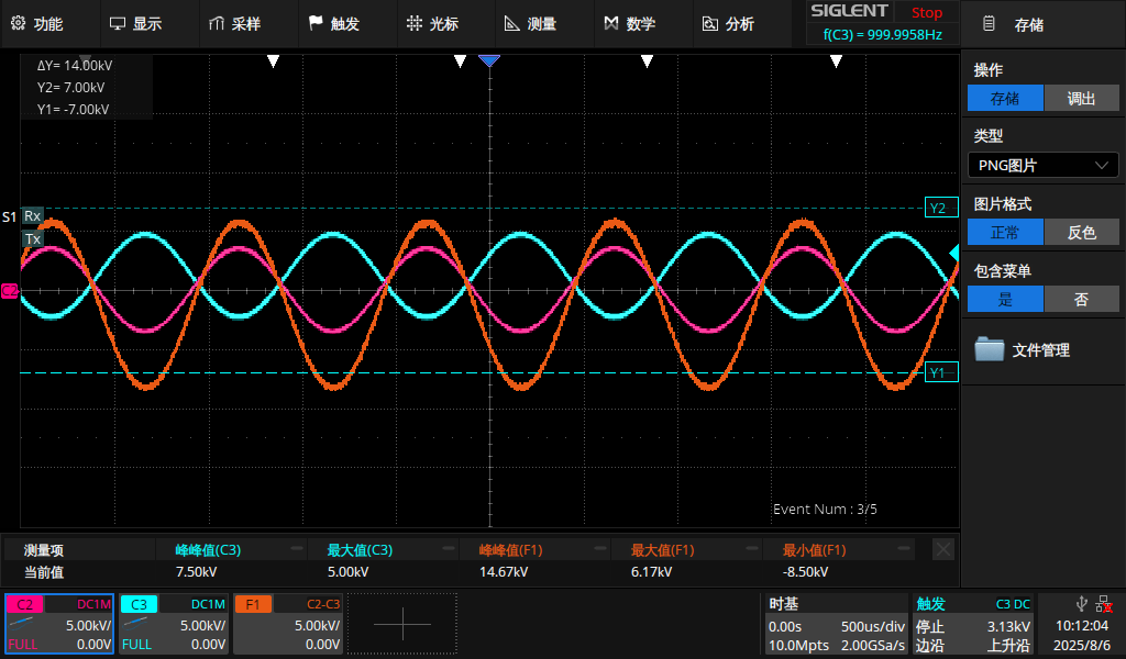
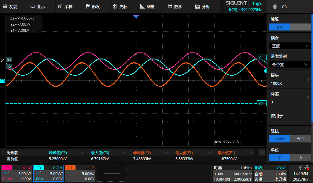
The waveform diagram provides a visual means to determine whether limits are exceeded. In the diagram, Y1 and Y2 represent the constraint boundaries (±7kV). Ensure that all three waveforms remain within these boundaries:
C2 Waveform: Input terminal A voltage relative to ground
C3 Waveform: Input terminal B voltage relative to ground
F1 Waveform: Differential mode voltage (A-B)
Operating conditions
①Differential mode voltage exceeds limit
Phenomenon: Both C2 and C3 waveforms fall within the Y1-Y2 range (A and B meet ground voltage compliance), but the F1 waveform exceeds the Y1-Y2 boundary (differential mode voltage is out of tolerance).
Consequence: Differential mode voltage exceeding the specified limit may lead to inaccurate measurement results.
②Input terminal to ground voltage exceeds limit
Symptom: The F1 waveform falls within the Y1-Y2 range (differential mode voltage compliance), but the C2 or C3 waveform exceeds the boundary (e.g., A-to-ground voltage is out of limits).
Consequence: This constitutes overvoltage operation, posing an immediate risk of probe damage.
4. Summary: The Key to Proper Use
Regardless of the differential probe type, two conditions must be simultaneously satisfied:
The voltage at each input terminal relative to ground must not exceed the specified limit.
The differential mode voltage between the two input terminals must not exceed the specified limit.
For the N1140A, this means ensuring that the voltages at terminals A and B relative to ground, as well as the differential mode voltage between A and B, all remain within ±7kV (with all three waveforms confined within the Y1-Y2 constraint lines). This forms the foundation for achieving safe and accurate measurements.